10+ ne555 block diagram
Ne555 testing capacitor consider electronicshub. The 555 is initially coupled as a low-frequency oscillator in order to command the voltage at pin 5 of the second 555 IC which is a control pin.

555 Timer Ic Wikiwand
NE555 is an 8-pin.
. Internal block diagram 1 The 555 timer IC is an integrated circuit chip used in a variety of timer delay pulse generation and oscillator applications. The following figure shows the functional diagram of timer IC 555. Circuit touch switch diagram 555 timer simple using alarm electronic ic led wiring circuitdigest projects digest circuits diagrams.
NE555SA555SE555 BLOCK DIAGRAM VCC 5kW COMP DISCHARGE THRESHOLD CONTROL VOLTAGE R FLIP-FLOP 5kW Q COMP OUT TRIGGER S INHIBIT RESET 5kW RESET S. A standard 555 Timer IC package includes 25 transistors 15 resistors and 2 diodes. NA555 NE555 SA555 SE555 PRECISION TIMERS SLFS022GSEPTEMBER 1973REVISED MARCH 2008 V CC 5 V to 15 V T A 25C unless otherwise noted NA555 SE555 NE555.
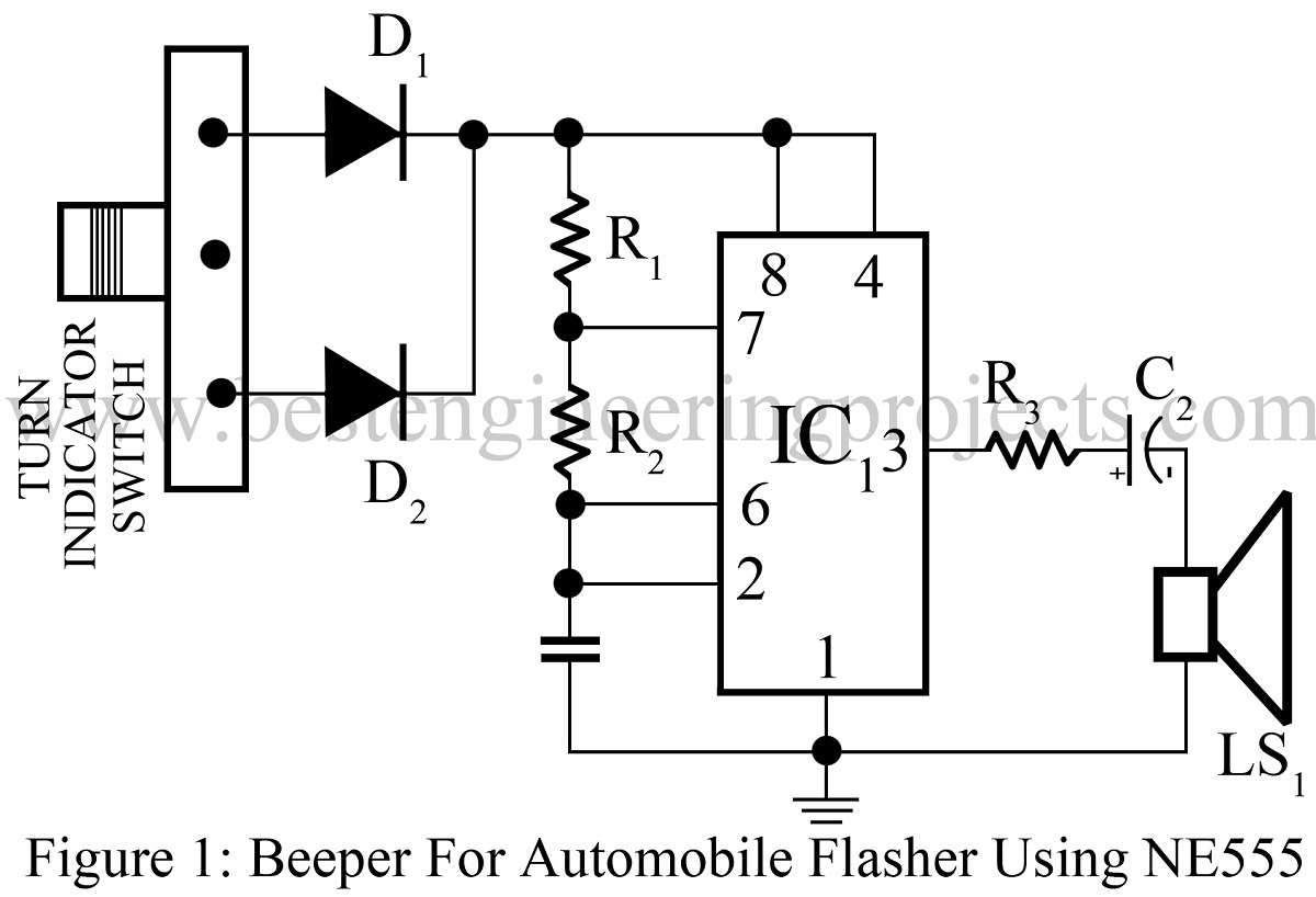
Maximum operating frequency greater than 500 kHz. The 555 Timer is used in this project to function in the Astable Multivibrator Mode. The circuit principle is shown in Figure 1.
Between the supply voltage VCC and the ground. As shown in figure IC555 includes two comparators one RS flip-flop and other few discrete components like transistors. 555 Timer IC-Block Diagram-Working-Pin Out Configuration-Data Sheet.
Timing from microseconds to hours. Represented with a block diagram it consists of 2 comparators a flip-flop a voltage. The 1K Resistor 50K POT and 01F Capacitor.
555 Timer Schematic. The attachment is the NE555 circuit intelligent design software which takes the NE555 chip as the core to design different intelligent control circuit software. 555556 Timer Functional Block Diagram capacitor voltage exceeds 23 of the supply the threshold comparator resets the flip-flop which in turn drives the output to a low state.
Figure 1 long delay circuit diagram of 555 time base circuit. A 12V DC source is used to power the entire circuit including the 555 timer. NE 555 timer ic pin diagram.
IC 555 Pin Diagram Description configuration Pinout. The following image depicts the block diagram of the PWM based LED Dimmer using 555 Timer IC. Heres the internal schematics of 555 Timer which consists of 25 transistors 2 diodes and 15 resistors.
Working of PWM LED Dimmer using 555. The root of the second oscillator. Operates in both astable and monostable modes.
The IC 1555 time base circuit is connected to a self-excited multivibrator with. The NE555 contains 24 bipolar transistors two diodes and 15 resistors that form six functional blocks. The 555 timer IC is a very cheap popular and useful precision timing device which can act as either a simple timer to generate single pulses or long time delays or as a relaxation.
50 Top 555 Timer Ic Projects Engineering Projects

How Does Ne555 Timer Circuit Work Datasheet Pinout Eleccircuit Com Timer Electronic Circuit Projects Circuit Diagram

555 Timer Ic Wikiwand

555 Timer Ic Wikiwand

555 Timer Ic Wikiwand

Pin On 555 Circuits

555 Timer Ic Wikiwand

555 Timer Ic Wikiwand

Icstation Ne555 Duty Cycle And Frequency Adjustable Module

Homemade Diy Howto Make Simple Doorbell Circuit Using 555 Timer Schematic Diagram Included Diy Electronic Kits Diy Electronics Timer

Pin On Led Circuits Projects

50 Top 555 Timer Ic Projects Engineering Projects
50 Top 555 Timer Ic Projects Engineering Projects

How Does Ne555 Timer Circuit Work Datasheet Pinout Eleccircuit Com Electronic Circuit Projects Electrical Circuit Diagram Circuit
50 Top 555 Timer Ic Projects Engineering Projects

Speed Controller Using 555 Electronic Schematics Electronics Mini Projects Electronics Circuit

How Does Ne555 Timer Circuit Work Datasheet Pinout Eleccircuit Com Timer Circuit Countdown Timer